Concrete Defects
Concrete members can be used in three forms for bridge construction as stated below:
- Plain Concrete
- Reinforced Concrete (Cast in-situ and precast)
- Pre-Stressed Concrete (Post-Tensioned mainly)
Safety Concerns – The major concern to ensure the integrity of a concrete bridge component is mainly in the protection of its reinforcement or tendon from corrosion. An equally important but more minor concern is to ensure that the concrete segment of the component that usually acts to resist compressive forces is not undermined from carrying out its load-supporting function. Unattended corrosion of the reinforcing bars or post-tensioning tendons would imminently lead to a catastrophic failure.
Sources of Defects - In concrete, it can be as a result of the following:
- Lack of durability of the concrete, resulting from an improper composition of the concrete elements
- Poor placement practices
- Poor quality control
- Aggressive environmental factors
The most common concrete defects to watch out for are:
Corrosion of Reinforcement or Tendons
Since concrete is poor in providing resistance to tension, most designs essentially ignore the contributions of concrete in the tension regions of the load-transfer mechanisms, making the reinforcement the critical member in these sections. Therefore, any significant loss of a section of the reinforcement or tendon due to corrosion would significantly reduce the load-carrying capacity of the member.
Concrete provides protection to the reinforcement or tendon and maintains a good alkaline environment of about pH 13, which leaves the reinforcement in a passive state. When this alkalinity is compromised and drops below pH 10 through exposure to salt, oxygen, moisture, air or other chemicals, the process of corrosion is triggered and can accelerate fast.
The bridge inspection exercise, therefore, should diligently seek for any exposed reinforcement or tendon or for defects that would expose them to environmental conditions and thus exacerbate corrosion.
Measurement – Condition assessment should include extensive sketches of defects, including some level of quantification (eg. length, area, percentage measures) and determination of the degree of reinforcement section loss when corrosion is already in progress.
 |  |
 | |
Carbonation of Concrete
This chemical condition affects the durability of concrete and lowers the alkalinity of the concrete cover to the reinforcement. The expansion of the carbonate gel that results from the chemical reaction may produce cracks in the concrete, thus opening a fault line for further progression of carbonation, and consequently causing the reinforcement to become prone to corrosion. Carbonation does not actually harm the concrete directly nor reduce its strength. However, poor, and porous concrete with high permeability, high water-to-cement ratio, low cement content, short curing period, or poor consolidation makes the concrete susceptible. Its resulting effects on the concrete allow corrosion of the reinforcing steel to thrive.
 |  |
Alkali-Silica Reaction
This chemical attack on concrete durability is as a result of the reaction of the silica in certain aggregate types with the alkaline in cement to produce Alkali-Silica Gel. The expansion of the gel when mixed with moisture leads to cracking and delamination of concrete. Its effect may take about 5 to 10 years to appear.
 | |
 |  |
Cracks in concrete
So far, we have seen concrete cracks initiated by environmental conditions resulting in chemical reactions that lead to cracking of concrete. In addition to these, a concrete member can also crack due to overload situations while performing its structural functions. These cracks again expose the reinforcement to corrosion agents and should be eliminated.


The extent of the crack width measurements can be assessed against a scale such as shown below:
Type of crack | Crack Opening or crack width |
Hairline cracks | up to 0.1mm |
Minor cracks | 0.1 to 0.3mm |
Moderate cracks | 0.3 to 0.6mm |
Severe cracks | > 0.6mm |
Spalling of Concrete
This can be as a result of the chemical attacks previously mentioned. It can also be due to the expansive action of corroded reinforcement exposed from flexural or shear cracks that develop on the member as a result of overload or due to damage by vehicular or vessel impact forces usually at the exposed corners or edges, deck joints or construction joints. In all cases, spalling is characterized by the actual removal or detachment of chunks of the concrete member. Therefore, there is an appreciable loss of concrete section that must be noted and recorded.
|
|
|
|


Delamination of concrete
This is a discontinuity in the surface concrete that is substantially separated but not completely detached from the concrete below or above it. It may appear as a solid surface but can be identified by a hollow sound that is produced by tapping the concrete with a hammer. Delamination defects may be hard to detect in the field and should be assessed very carefully.
 |  |
Surface defects in concrete
A surface defect is not necessarily serious in itself, but is indicative of a potential weakness in concrete and needs to be captured during the inspection. Such defects may very well have serious traffic or bridge safety consequences if not treated. There are a few concrete defects under this category and they include:
- Concrete Segregation – due to the differential concentration of the components of mixed concrete.
- Cold joints – produced when there is a delay in the placement of successive pours of concrete.
- Surface Deposits:
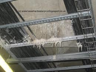
- Efflorescence – deposit of salts, usually white and powdery, resulting from a mixture of salt and water that oozes out to the surface through pores or cracks in the concrete.
 |  |
 |  |
- Exudation – Liquid or gel-like discharge through pores and cracks in the surface.
- Encrustation – A hard crust or coating formed on the concrete surface.
 |  |
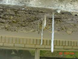
- Stalactite – A downward pointing formation hanging from the concrete surface, usually shaped like an icicle.

- Honey combing - Produced due to improper or incomplete vibration of the concrete, loss of moisture from formwork during concreting, which results in voids in the concrete. The existence of these voids constitutes a danger to the reinforcement embedded in the concrete member.


 |  |
Abrasion
Deterioration of concrete brought about by vehicles scraping against the concrete surfaces, such as the deck, kerbs, barrier walls, and piers.
 |  |
Slippery surface
Results from the polishing of the Conc. Deck surface by the action of repetitive vehicular traffic.

Steel Members
Similarly to concrete, the main damage process of steel is corrosion, but also fatigue is an important issue.
- Corrosion – There are different types of corrosion:
- Environmental corrosion – Affects metal in contact with soil or water and may be caused by the formation of a corrosion cell due to moisture content, oxygen content, de-icing salt concentrations, and accumulated foreign matter such as roadway debris and bird droppings.
- Bacteriological corrosion – Caused by organisms found in swamps, bogs, heavy clay, stagnant water, and contaminated water.
- Stress corrosion – Results from exposure of an increased portion of the metal at the grain boundaries due to the action of tensile forces.
- Fretting corrosion – Appears on closely-fitted steel parts that are under vibration, and can be identified by pitting and a red deposit at the interface.
- Stray current corrosion – Caused by cathodic protection systems for pipelines or foundation piles, DC industrial generators, DC welding equipment, central power stations, large substations, electric railways, and railway signal systems.
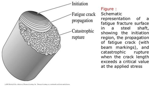
- Fatigue Cracking – Develops in steel member bridges due to repeated loadings. This type of cracking can lead to sudden and catastrophic failure. Out-of-plane distortion affecting member connections is a primary cause. Factors leading to the development of fatigue cracks include:
- The frequency of truck traffic (ADT)
- The age or load history of the bridge
- The magnitude of Stress range (variation in truck configuration & loading)
- Type of detail of the member (connections most susceptible)
- Quality of the fabricated detail (existence of stress concentration points to be avoided or minimized)
- Material fracture toughness (base metal and weld metal)
- Quality of Welds
- Overloads – Loads which exceed that for which the member or structure was designed could lead to crack initiation at the overstressed locations. An overload situation may produce plastic deformation of the steel after exceeding its elastic limits and may progress to complete failure of the members in tension through elongation and “necking” --- a decrease in cross section --- and in compression members through buckling.
- Vehicular Damage – This is damage caused by impact from a vehicle or vessel. Indications of vehicular damage include dislocated and distorted members.
Steel Defects
Corrosion
Corrosion is the deterioration of steel by chemical or electrochemical reaction resulting from exposure to air, moisture, industrial fumes and other chemicals. Corrosion will occur if the steel is not protected or if the protective coating wears or breaks off. It can result in the loss of section as it progresses and becomes flaky and delaminates, exposing pitted surfaces.
Permanent Deformation
It can take the form of i. Bending, ii. Buckling, iii. Twisting, iv. Elongation, v. combinations of these. It may be caused by overloading, vehicular collision, or inadequate or damaged intermediate lateral supports or bracing:
- Bending Deformation – Usually associated with the flexural members.
- Buckling Deformation – Usually associated with the compressive members, e.g. web, flanges of beams, plate girders, or box girders.
- Twisting Deformation – Rotation of the member about its longitudinal axis, and is usually as a result of eccentric transverse loads on the member.
- Axial deformation – Occurs along the length of the member and is normally associated with internal tension forces.
Cracking
This is a linear fracture of the steel. It is mainly produced due to fatigue and can, under certain conditions, lead to brittle fracture.
- Brittle Fracture – A crack completely through the component that usually occurs without prior warning or plastic deformation. Brittle fracture may result in fatigue-prone details after the initial fatigue cracking.
- The primary factors leading to fatigue cracking are – The number of applied stress cycles, which is a function of Average Daily Traffic (ADT), the magnitude of the stress range (i.e. live load range and fatigue strength of the connection).
- The locations susceptible to cracking in steel members are:
- Locations of Stress Concentration e.g. Weld/Joint members.
- Locations with Loss of Sections due to corrosion.
- Point of Stress Concentration due to poor quality of fabrication details.
- Welded details are more prone to cracking than bolted and riveted details, but bolts and rivets can also crack. However, the cracking is unlikely to extend to the adjacent members and will just weaken the joint.

Note: Cracks perpendicular to the direction of stress are very serious, with those parallel being less so, but can still turn into perpendicular as they run unchecked.
Timber Members
- Wood Decay – untreated wood or portion thereof is vulnerable to damage by living organisms and predators including:
- Fungi – Plants that feed on the cell walls of a wood
- Parasites – These tunnel in and hollow out the insides of timber members for food and shelter (e.g. termites, carpenter ants, powder-post beetles, marine borers, and caddisflies).
- Chemical Attack – Chemicals do not cause structural degradation to wood, but animal waste can cause damage. Also, strong alkalis will destroy wood fairly rapidly.
- Checks – Partial-depth separation of fibres, of which cracks or fissures do not extend through the piece from one face to face of the wood.
- Splits – Full-depth cracks extending from face-to-face of the wood.
- Knots - A knot is a particular type of imperfection in a piece of wood; it affects the technical properties of the wood, usually reducing the local strength and increasing the tendency for splitting along the wood grain.
- Cracks - Cracks resulting from overstress.
- Damage from other Sources – Wood deterioration can also be caused by:
- Fire
- Impact or collision
- Abrasion or mechanical wear
- Overstress (leading to cracks)
- Weathering or warping
Masonry Members
- Weathering – Occurs when a hard surface degenerates into small granules, giving stones a smooth, rounded look.
- Spalling – Occurs when small pieces of rock or bricks break out or chip away.
- Splitting – Occurs when seams or cracks open up in rocks or bricks, eventually breaking them into smaller pieces.
- Bulging – A change in shape or bending of the face of a masonry wall, usually due to the soil behind pushing part of the face outwards (can happen in abutments, retaining walls, or barrels of spandrel walls of masonry arch bridges). Vehicular impact can cause masonry parapets to bulge.
- Poor Pointing – Refers to the mortar between the bricks or stones. The mortar can be worn away by the river or rainwater, running down the face of the masonry.
- Cracking – Can be caused by overloading, vibration or impact from traffic, by failure of the foundation, temperature changes, or by wetting and drying.
- Spandrel Wall Separation – May occur in arched masonry bridges when lateral forces acting on the spandrel wall result in the spandrel slipping over the arch back. It is usually a sign that the bridge is overloaded or over-ballasted.
- Ring Separation – May occur in arched masonry bridges as result of inter-ring stresses caused by either settlement or increased loading over time. Chemical action may cause the arch barrel to deteriorate, with individual rings contracting and separating from their adjacent and/or subsequent rings, leaving voids in the worst cases.
- Distortion – Occurs as a result of the development of transverse cracks in masonry bridge members.
Some causes of the above forms of deterioration include:
- Presence of Chemicals – Gases and solids dissolved in water often attack rocks and the cementing compounds between the rocks.
- Volume Changes – Seasonal expansion and contraction can cause tiny seams to develop, weakening the rock.
- Frost and Freezing – Water freezing in the seams and pores of rocks can spall and split the rock.
- Abrasion – Mainly due to wind and waterborne particles.
- Plant growth – Roots and stems growing in crevices or joints can exert a wedging force. Also, lichen and ivy can chemically attack stone surfaces.
- Marine borers – Rock-boring molluscs attack rocks by means of chemical secretions.
- Backfill saturation – Saturated backfill soil may lead to excessive pore pressures in the backfill soil, which can in turn lead to excess active pressure on the masonry walls and eventual failure of the walls.
Aluminium Members
- Fatigue cracking – The combination of high stresses and vibration caused by wind produces fatigue.
- Pitting – Aluminium can pit slightly, but this condition rarely becomes serious.
General defects not related to bridge material
Scouring of Foundation
Scouring of foundation caused by excessive stream flows or changes in the alignment of the stream channel can result in the progressive settlement or movement of abutments and piers and consequently to total bridge collapse if unchecked. Scour is perhaps the biggest threat to the substructure and foundation components regardless of the material the structural component is made of. Exposure of the foundation components and erosion of the surrounding soil strata is a recipe for disaster and poses a serious safety hazard to the structural integrity of the bridge and must be avoided or corrected immediately.
Scour Modes are in three main forms:
- General Scour – Occurs naturally in stream channels and includes the aggradation and degradation of the stream bed, which may occur as a result of changes in the hydraulic parameters governing the channel form such as changes in the flow rate or changes in the quantity of sediment in the river channel.
- Contraction Scour – Occurs as a result of the reduction in the channel’s cross-sectional area that arises due to the construction of structures such as bridge piers and abutments. It manifests as an increase in flow velocity and the resulting bed shear stresses, thus causing scour.
- Local Scour – Occurs around individual bridge piers and abutments.
 |  |
Movement Deflection
Usually, movements in bridges can be detected and should be recorded by observing total closures or excessive openings of deck expansion joints:
- Bearing or jamming up between the end of the Superstructure and Abutment ballast wall, with the associated cracking and spalling of concrete that will occur.
- Cracking or excessive settlement of the approach embankments or heaving at its toe.
- Scour causing undermining of the foundation components.
- Out-of-verticality of columns, piers, abutments, and service or utility poles.
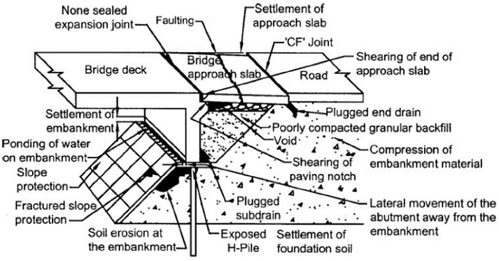
Conditions at the Approach
An Embankment is used to provide a stable road between the bridge and the surrounding ground. Often, it is also required for providing horizontal, and sometimes vertical support for the Abutment and foundation. The most common defect associated with the Approach is excessive settlement adjacent to the bridge abutment, which causes unsatisfactory riding quality and possible damage to the deck and expansion joints. Excessive settlement at the bridge approach span interface with the main bridge structure resulting in a “bump” is a safety hazard for the vehicular traffic and its users. Possible reasons for this failure include:
- Poorly compacted embankment
- Continuing settlement of the underlying ground
- Erosion due to blockage or inadequate drainage
 Embankment
Expansion Joints
They are installed to allow the horizontal movement of bridge components resulting from environmental forces and vehicular traffic loading. Furthermore, they are often designed to protect the bridge underneath from the ingress of water or salts and other corrosive chemicals through the bridge deck by the installation of rubber seals or its equivalent. Two of the main effects to check at the expansion joints during the inspection are the excessive opening of the joint resulting from the horizontal movement and for broken rubber seals.
Vegetation
Uncontrolled and excessive growth of vegetation under or adjacent to the bridge does not in itself cause damage to the bridge. It can, however, cause fire hazard, blockage to the waterway, and build-up of debris and moisture around abutments and bearings.
Debris
The build-up of debris on the upstream side of the bridge can cause the following adverse effects on the bridge:
- Imposed loads on the bridge during flooding, which it was not designed for.
- Cause blockage of the bridge waterway during flooding, which can exacerbate problems of scour, undermining of foundations, flooding, and in extreme cases, total blockage and diversion of the watercourse.
- Build-up of debris below a bridge may become a fire hazard, increasing the risk of fire damage to pile and pier caps or bent.
Drainage
Ineffective bridge drainage may affect the bridge in several ways:
- Flooding of the bridge deck, which may create serious traffic hazard.
- Uncontrolled water ingress over concrete or steel surfaces or bearings below the deck level may result in corrosion or unsatisfactory performance of the bearings.
- The debris carried by drainage flows may build up in areas, retain moisture and promote corrosion.
- Uncontrolled discharge from the deck can cause erosion of Approaches and Batters, and possibly undermine the foundation.
- Leakage of bridge decks through joints and cracks may cause unsightly staining of beams, piers, and abutments.
- Inadequate collection of drainage from the bridge approaches can also cause erosion, piping, and washout or scour of the Approach Embankment and Batter slopes.
Utility and Services
Utilities, including lightings and pipelines, are often found on bridges and must be inspected for their functional integrity, especially with respect to the bridge structure.
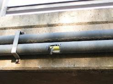 Pipe lines