Collection of Inventory Information
Bridge inventory information can be collected at the office or during inspections, which are commonly carried out after construction or reconstruction of a bridge, but can also be done directly before the condition assessment. The main idea of the inventory information is to prepare the background database for the maintenance and rehabilitation planning. Without correct inventory information it is not possible to carry out the condition assessment.
The main purpose of it is to obtain inventory data required for network level planning and informed decision making. The inventory information will be collected with standardized series of data items that enable geometry, construction, and function of a bridge to be identified and described.
Inventory Information Collection
The main activity is to collect the relevant information without on-site visit is locating, finding, and reviewing the bridge structure files and plans. The success of this type of inventory inspection is largely dependent on the effort put into documenting of previous design and building process. The data collection activities include reviewing the bridge structure files, plans and documents to identify the main measurements, possible components, and elements. If the data is collected by personnel without proper preparation, the basic components and parameters with terminology is presented to increase the basic knowledge level.
Possible sources of information about the bridge include:
- The “Design” and “As-built” bridge plans. The bridge plans contain information about the bridge type, the number of spans, the use of simple or continuous spans, and the materials used to construct the bridge. They also contain information about the presence of composite action between the deck and girders, the use of framing action at the substructure members, and the kind of connection details used. The year of construction and the design loading are also usually contained in the bridge plans.
- Previous inspection reports that are done prior to the development of the system. Previous inspection reports provide valuable information about the history of the bridge, documenting its condition in previous years. This information can be used to determine which components and elements of the bridge warrant special attention. It also allows to compare the current levels of deterioration with those noted during the previous inspections to help determine the rate of deterioration.
- Maintenance and repair records that are done prior to the development of the system. Maintenance and repair records allow the inspector to report all subsequent repairs during the inspection phase, noting the types, extent, and dates of the repairs.
- Rehabilitation/Retrofit plans. Rehabilitation plans show modifications and replacements performed on the structure. Just as with the design plans, “As-built (or record) drawings are preferable.
- Geotechnical data if available. Geotechnical data provides information about the foundation material below the structure. Sand, silt, or clay is more susceptible to settlement and scour problems than is rock. Therefore, structures founded on these materials should generally be given special attention with respect to foundation and scour issues than those founded on rock.
- Hydrologic data if available. Hydrologic data provides information about the shape and location of the channel, the presence of protection devices, flood frequencies, and water elevations for various flood intervals. This information is necessary for scour evaluation, expected flood flows, and water velocity.
- Roadway plans. Roadway plans may provide some information if the structure plans are not available.
Although the information collection without inspections is a possibility, it is still suggested to check and enter the information during the inventory inspection. Without on-site visits, it is possible to collect inventory information more than ten structures in a day at an average.
The main activity is to collect the relevant information only with inspections defining, counting, measuring, and recording the bridge structure information. The success of this type of inventory inspection is largely dependent on the effort put in the inspections and taking correct photos for post processing in office. During inventory information collection inspection, the main objective is to measure main dimensions (length, width, span length etc.) and define all bridge elements and typologies. Inventory information is the most important part of the database, because without the correct information the system is useless. Based on the collected information, it is possible to distinguish the different types of bridges, present the quantifiable values of structures, and do the initial analysis of bridge network. Inventory information is collected only for bridges and bigger culverts (overall length of over 1.8m).
The data collection can be divided into two separate parts: (1) Dates, location, and measurements, (2) features and elements. The sequence for collecting inventory information is as follows:
- Search for the bridge in the database (if one exists) or name the bridge after the location (village, road etc.)
- Define the location or save the bridge GPS location.
- Measure the main dimensions (Figure 3b. Main transverse dimensions of a bridge. Examples of a few cases of different bridge types)
- Define the elements (Chapter 4.1.1)
Overall Bridge Identification Information
| Region | According to bridge location |
| Province (Drop down list for Region) | |
| District (Drop down list for Province) | |
| Bridge ID code/Number | According to numbering system |
| Bridge Name | Name of bridge |
| Inspector's Name | |
| Date of Inspection | dd/mm/yyyy |
| Source of information | Field measurements |
| Design Drawings/Map/Plan | |
| As built drawings | |
| 3d Model/Point cloud | |
| Other - add comment |
Bridge Location
The location data (Table 4.2. Bridge location details to be collected) is collected in the same format for all the bridges.
The road section data available in the database should be considered as primary location reference data to be used during the data collection. The referencing data should be verified.
The chainage data should be collected according to Figure 2. If available, GPS coordinates should be added.
 Measurement points of the Chainage (Flow Direction: Upstream to downstream)
| BRIDGE LOCATION DETAILS | |
|---|---|
| Road ID code | The ID of the road on which the bridge is located |
| Road Name | The name of the road on which the bridge is located |
| Road address (distance from the road beginning in km) | Distance from the start of road in kilometres |
| Carriageway (1 or 2) | |
| GPS coordinates start chainage | |
| GPS coordinates end chainage | |
| Feature Crossed | River Name |
| Road Number | |
| Creek | |
| Minor Creek/stream | |
| Swamp | |
| Sea (exposed) | |
| Estuary (salt water) | |
| Other (specify) | |
| Detour length for the bridge [km] | Approximate alternative distance of getting to other side of the bridge |
| Detour time for the bridge [h] | Approximate detour time in hours |
| Alternative route | Description of the alternative route to other side of the bridge |
| Construction year | |
| Rehabilitation year, last | |
| Rehabilitation type, last | Repair |
| Strengthening | |
| Reconstruction | |
| Other - add comment | |
Bridge Geometry
The bridge measurements should be recorded with the resolution of 0.1 m. Preferably on site, but design information can also be a good input. The following Figure 3a and 3b illustrate the main longitudinal and transverse dimensions of a bridge with a few case examples.
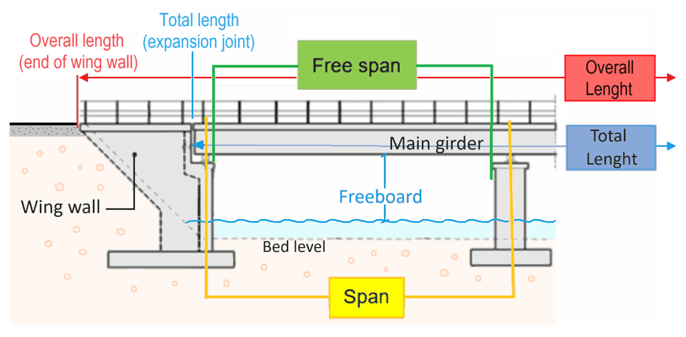 Main longitudinal dimensions of a bridge. The overall length is measured from the end of a wingwall to the other side’s wingwall’s end, while the total length is measured without the wingwalls, the distance between the last expansion joints, the expansion joints themselves counted out.
Below are the main transverse dimensions of a bridge, with some examples of a few cases of different bridge types.
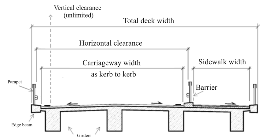 The carriageway width can be considered as kerb to kerb measure, even though sometimes there may be white edge lines marked on the bridge. Sidewalk width is the width of the foot path unless narrowed further by parapets or barriers. Horizontal clearance is the maximum oversize width that can pass the carriageway, in this case from parapet to parapet. Vertical clearance is unlimited.
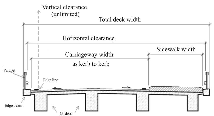 In this case the carriageway width is from the kerb until the kerb or clearly elevated and thus separated sidewalk. In this case the horizontal clearance for oversize transport is from parapet to parapet, spanning over the sidewalk.
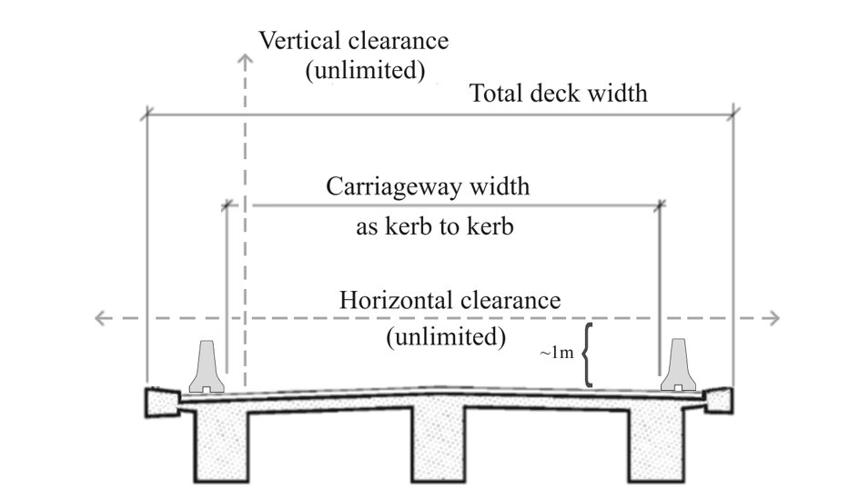 In this case the carriageway is bordered with concrete barriers. However, in addition to unlimited vertical clearance, also the horizontal clearance is considered unlimited for oversize transport as these barriers stay low and there is nothing to block the clearance at over 1m height. Therefore, the bridge does not pose a width limit for an oversize cargo loaded on a trailer or other special equipment transport.
 In this example of a half through H-section truss bridge there is no kerbs or dividing parapets, so the carriageway width is measured from the edge of the deck to the other edge.
 In this example of a full box truss bridge the carriageway width is measured from the kerb/barrier to the edge of the deck. Vertical clearance is not anymore unlimited in this type of a bridge, as it’s usually limited by the top chord struts, or even lower because of the diagonal top chord braces as in this example. Note that the clearance is measured at the lowest point over the carriageway. If carriageway is marked then at the lowest point between the edge lines, but if not marked, at the lowest point within the whole carriageway. Horizontal clearance is between the parapets, spanning over the divider, as the concrete barrier is less than 1m high.
Bridge Inventory - General Data
| Type of crossing | Bridge |
| Viaduct | |
| Light traffic bridge | |
| Underpass | |
| Culvert | |
| Ford | |
| Special - add comment | |
| Other - add comment | |
| Other - add comment | |
| Principal feature (traffic above) | Car traffic |
| Pedestrian/light traffic | |
| Wildlife | |
| Other – add comment | |
| Structural (Span) Form of the Bridge | Box culvert cell |
| Brick (Arch) | |
| Cantilever and suspended span | |
| Concrete pipe culvert | |
| Continuous | |
| Corrugated steel culvert | |
| Integral | |
| Partially continuous | |
| Rigid-frame/Fixed end | |
| Simply supported | |
| Tubular | |
| Other – add comment | |
| Skew angle | |
| Number of car lanes on bridge | |
| Clearances on road carried (Principal Feature) [m] | 1. Vertical Clearance – height between the top of the deck to the underside of any transverse element. No limits leave blank. |
2. Horizontal Clearance – distance between the inside faces of the outer elements (truss or parapet). No limits leave blank. | |
| Overall Length [m] | Distance between the furthermost elements of a bridge |
| Total Deck Length [m] | Along the direction of the road, the distance between the outer edges of the abutment expansion joints. |
| Total deck width [m] | Distance between outermost edges of deck |
| Sidewalk width Left [m] | Total sidewalk/walkway width on the left |
| Sidewalk width Right [m] | Total sidewalk/walkway width on the right |
| Carriageway width [m] | Kerb to kerb width |
*Skew angle can be determined using the Compass feature on the Tripltek tablet (Outdoors folder): Angle (acute or obtuse) subtended by Route Direction & Normal to the Flow Direction.
Bridge Elements - Surface - Before Bridge
| Approach way (cover) material | Asphalt concrete |
| Surface dressing | |
| Concrete | |
| Earth | |
| Gravel | |
| Approach way (Side) | Kerbs |
| Safety barrier | |
| Drainage gully | |
| Approach way Material - Kerbs | Concrete (on site) |
| Concrete (Precast) | |
| Masonry | |
| Approach way Material – Safety barrier | Aluminium fixed |
| Aluminium flexible | |
| Concrete | |
| Concrete & steel | |
| Steel | |
| Timber (Normal) | |
| Approach way Material – Drainage gully | Concrete (on site) |
| Concrete (Precast) | |
| Masonry | |
| Steel | |
| Plastic | |
| Approach way width [m] | Width of the road structure or kerb to kerb |
| Overlay/Deck wearing surface (Road) | Asphalt concrete |
| Surface dressing | |
| Concrete | |
| Steel plates/Grating | |
| Timber planks | |
| Bitumen | |
| Overlay/Deck wearing surface (Sidewalk) | Asphalt concrete |
| Surface dressing | |
| Concrete | |
| Steel plates/Grating | |
| Timber planks | |
| Bitumen | |
| Signs (Bridge Sign) | Yes/No |
| Signs (Reflectors) | Yes/No |
| Parapet | Yes/No |
Span Information
(Note that information inserted for Span 1 continues throughout the spans unless it is unique for a span and is changed during the inspection – span length normally on multi-span bridges).
Span 1 - Contains Near Abutment Data
| Number of Spans | |
| Span Length (m) | The span length should be defined for every span |
| Expansion Joints | Buried |
| Steel – prefabricated | |
| Nosing | |
| Compression seal | |
| Rubber Extrusion | |
| Steel finger | |
| Sliding plate | |
| Reinforced elastomeric | |
| Elastomeric in metal runners | |
| Elastomeric strip seal | |
| Elastomeric box seal/Modular | |
| Cantilever Comb and Tooth | |
| Steel angle | |
| Other – add comment | |
| None | |
| Abutment height | |
| Exposed height of the abutment [m] | |
| Longitudinal width of the abutment [m] | |
| Abutments | Gravity |
| Pile (stub abutment) | |
| Bank-seated (stub abutment) | |
| Wall and counterfort | |
| Spill through abutment | |
| Full height integral | |
| Integral with pile foundation | |
| Integral with spread footing | |
| Gabions | |
| Reinforced earth abutment | |
| Abutment cap | Concrete (on site) |
| Concrete (Precast) | |
| Timber (Normal) | |
| Steel | |
| Bearings | Lubricated steel plates |
| Neoprene rubber sheet | |
| Pot-cum-PTFE slided-guided/free | |
| Pot-cum-PTFE fixed | |
| Single roller | |
| Roller nest | |
| Segmental rocker | |
| Segmental rocker nest | |
| Rocker | |
| Pinned rocker | |
| Plain neoprene pads | |
| Laminated neoprene pads | |
| Isolation | |
| Friction pendulum | |
| High dampening rubber | |
| Spherical pot | |
| Disc bearing | |
| Pin and link | |
| Unknown | |
| None | |
| Wing walls are part of abutment | Yes/No |
| Wing walls | Free standing |
| Strengthened/Reinforced | |
| Splayed | |
| Wing walls material (Free Standing & Splayed) | Concrete (on site) |
| Concrete (Precast) | |
| Timber (Normal) | |
| Masonry | |
| Wing walls material (Strengthened/Reinforced) | Soil |
| Gabions | |
| Masonry | |
| Reinforced earth wall | With relief culvert |
| Without relief culvert | |
| Reinforced earth wall materials | Concrete (Precast) |
| Geostrap | |
| Barriers | Vehicle restraint system |
| Hand rails | |
| Structural element | |
| Barriers material | Steel |
| Concrete | |
| Concrete and steel | |
| Timber | |
| Deck | Solid slab |
| Voided slab | |
| Truss | |
| Log | |
| Unknown | |
| Deck material – Solid slab & Voided slab & Deck edge beam | Concrete (on site) |
| Concrete (Precast) | |
| Concrete (Pre-tensioned) | |
| Concrete (Post-tensioned) | |
| Timber (Normal) | |
| Timber (Tensioned) | |
| Deck material - Truss | Steel |
| Timber (Normal) | |
| Deck material - Log | Timber (Normal) |
| Deck (edge beam) | Concrete (on site) |
| Concrete (Precast) | |
| Concrete (Pre-tensioned) | |
| Concrete (Post-tensioned) | |
| Timber (Normal) | |
| Timber (Tensioned) | |
| Main Girder | Bailey |
| Box Girder | |
| Girder | |
| Deck truss | |
| Through truss | |
| Log | |
| Slab | |
| Arch | |
| Culvert | |
| Frame | |
| Main Girder Material - Bailey | Standard |
| Super | |
| Compact 100 | |
| Compact 200 | |
| Universal | |
| Other | |
| Main Girder Material – Box Girder & Girder | Concrete (on site) |
| Concrete (Precast) | |
| Concrete (Segmental) | |
| Concrete (Post-tensioned) | |
| Steel | |
| Timber (Tensioned) | |
| Main Girder Material – Deck truss & Through truss | Steel |
| Timber (Normal) | |
| Main Girder Material - Log | Timber (Normal) |
| Main Girder Material - Slab | Concrete (on site) |
| Concrete (Precast) | |
| Concrete (Pre-tensioned) | |
| Concrete (Post-tensioned) | |
| Timber (Normal) | |
| Timber (Tensioned) | |
| Steel | |
| Main Girder Material - Arch | Masonry |
| Concrete (on site) | |
| Concrete (Precast) | |
| Concrete (Pre-tensioned) | |
| Concrete (Post-tensioned) | |
| Steel | |
| Composite (steel + soil) | |
| Main Girder Material - Culvert | Concrete (on site) |
| Concrete (Precast) | |
| Steel | |
| Composite (steel + soil) | |
| Plastic | |
| Main Girder Material - Frame | Concrete (on site) |
| Concrete (Precast) | |
| Concrete (Pre-tensioned) | |
| Concrete (Post-tensioned) | |
| Steel | |
| Secondary member | Girder |
| Beam (diaphragm) | |
| Bracing | |
| Cable | |
| Log | |
| Secondary member Material – Girder & Beam (Diaphragm) | Concrete (on site) |
| Concrete (Precast) | |
| Steel | |
| Secondary member Material - Bracing | Steel |
| Timber (Normal) | |
| Secondary member Material - Cable | Steel |
| Secondary member Material - Log | Timber (Normal) |
| Timber (tensioned) | |
| Other member | Vertical restraint system |
| Seismic dampers | |
| Drainage | Outlet pipes |
| Downspout pipes | |
| Deck drains | |
| Pipe | |
| Drainage Material - Outlet pipes & Downspout pipes | Steel |
| Stainless Steel | |
| Plastic | |
| Drainage Material – Deck drains & Pipe | Concrete (on site) |
| Concrete (Precast) | |
| Steel | |
| Plastic | |
| Construction joints/Hinges | Steel |
| None |
For Multi-span bridges with 'N' spans - Spans 2 to Span (N-1)
As per previous table but with Abutment data removed and the following Pier data added:
| Piers | Solid wall |
| Multiple column | |
| Single column | |
| Gravity | |
| Trestle column with bracing | |
| Pile | |
| Cantilever | |
| Integral | |
| Piers material – Solid wall, Multiple column, Single column | Concrete (on site) |
| Concrete (Precast) | |
| Composite (steel & Concrete) | |
| Composite (masonry & concrete) | |
| Timber (Normal) | |
| Steel | |
| Masonry | |
| Piers material - Gravity | Concrete (on site) |
| Piers material - Trestle column with bracing | Steel |
| Masonry | |
| Composite (masonry & concrete) | |
| Piers material - Pile | Concrete (on site) |
| Concrete (Precast) | |
| Composite (steel & Concrete) | |
| Composite (masonry & concrete) | |
| Timber (Normal) | |
| Steel | |
| Piers material – Cantilever, Integral | Concrete (on site) |
| Steel | |
| Composite (steel & Concrete) | |
| Pier Cap | Concrete (on site) |
| Concrete (Precast) | |
| Timber (Normal) | |
| Steel | |
| Clearances underneath [m] Vertical Clearance /Measured freeboard | |
| Clearances underneath [m] Horizontal Clearance (free span) | |
| Bearings 1 & 2 (each pier can have 2 sets of bearings which may be different types) For continuous decks over the pier with only 1 bearing, Bearing 2 shall be “None” | Lubricated steel plates |
| Neoprene rubber sheet | |
| Pot-cum-PTFE slided-guided/free | |
| Pot-cum-PTFE fixed | |
| Single roller | |
| Roller nest | |
| Segmental roller | |
| Segmental rocker | |
| Segmental rocker nest | |
| Rocker | |
| Pinner rocker | |
| Plain neoprene pads | |
| Laminated neoprene pads | |
| Isolation | |
| Friction pendulum | |
| High dampening rubber | |
| Spherical pot | |
| Disc bearing | |
| Pin and link | |
| Unknown | |
| None | |
| Bearing movement indicator | Yes/No |
End Span 'N'
As per Span 1 table (with far Abutment data) with the Pier Elements from previous table added.
Bridge Elements - Surface - After Bridge
As per Bridge Elements - Surface - Before Bridge table.
Bridge Elements - Outer
| Riverbed protection | None |
| Riprap | |
| Gabions/Reno mattress | |
| Concrete | |
| Filter point mattress | |
| Articulated block mattress | |
| Not known | |
| Training | None |
| Sheet piled wall | |
| Gabion groins | |
| Timber groins | |
| Filter point mattress | |
| Articulated block mattress | |
| Embankment and gabions | |
| Embankment and riprap | |
| Scour protection | None |
| Sheet piled wall | |
| Gabion groins | |
| Timber groins | |
| Filter point mattress | |
| Articulated block mattress | |
| Riprap | |
| Gabions/Reno mattress | |
| Not known | |
| Spread footings | Concrete |
| Piles | Concrete |
| Steel/Concrete (Circular) | |
| Caissons | Steel (Circular) |
| Steel (H section) | |
| Concrete (bored cast in situ under rugged) | |
| Concrete (driven precast) | |
| Concrete (precast and prestressed) |
General Features and Elements
The Bridge Inspector ought to be familiar with the components and elements of the bridge to be inspected ahead of arriving at the site. To provide a reasonable level of confidence in the safety of the bridge, knowledge of the structure and good engineering judgment by the inspector is necessary. The relevant Templates for element information input is presented in Annexes C, D and E. Examples of most common Bridge Construction Types are presented next.
 Girder Bridge
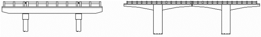 Cantilever bridge
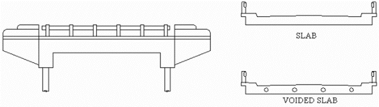 Slab bridge
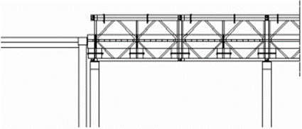 Bailey bridge
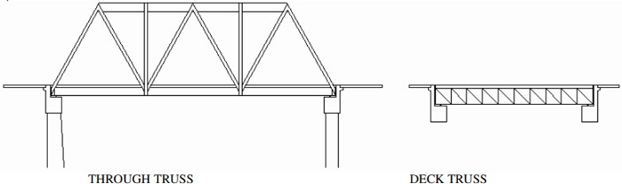 Truss bridge
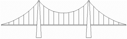 Suspension bridge
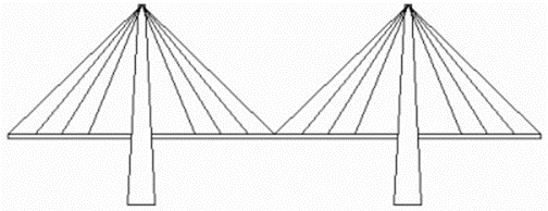 Cable stayed bridge
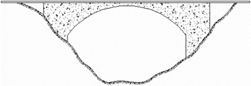 Arch bridge
The Bridge Inspector should be acquainted with the main components of the bridge. The overall position of elements is presented below.
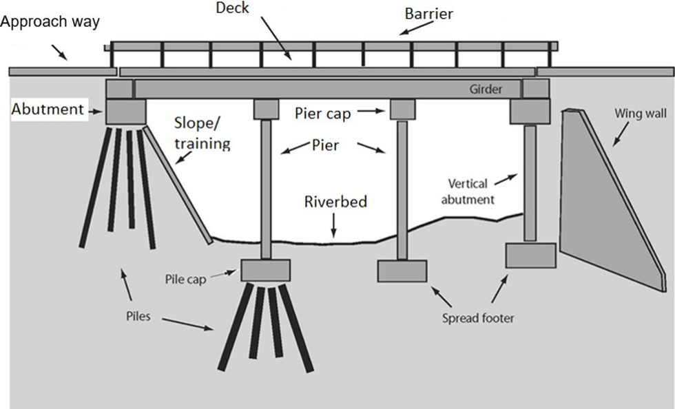 Typical bridge element locations
Elements
Surface
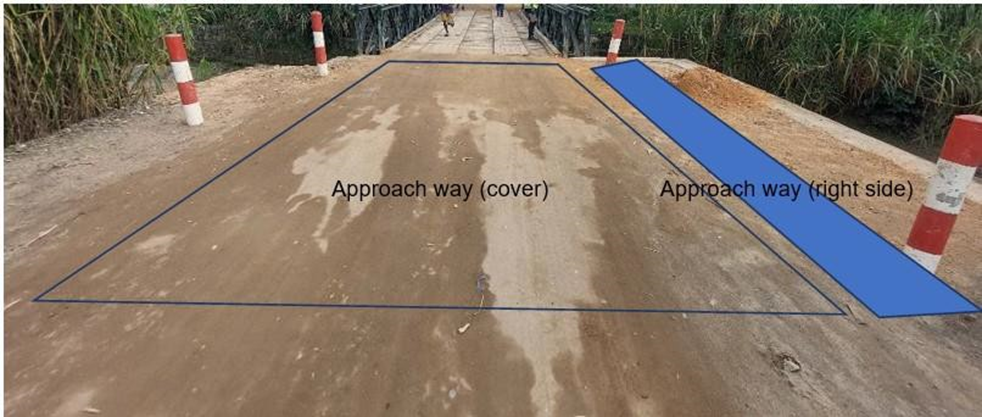
- Approach way (cover) 10 metres of roadway before and after the structure.
- Approach way (side) 10 metres of roadway sides before and after the structure.
- Overlay/Deck wearing surface –top layer of the bridge, mainly influenced by the traffic.
- Barrier and handrails – safety elements on the sides of a structure.

- Signs – related to traffic management, typically sign with a bridge name.
- Parapet
Superstructure
- Deck – load-bearing element that distributes the traffic load from top-layer to girders.
- Edge beam – side of a bridge deck that protects main girders from water and other pollutants.
- Expansion joints – connection points of a road and a bridge or different spans of a bridge. Allows the structure to deform longitudinally without causing additional stresses.
- Main girder – main load-bearing element
- Secondary member – load bearing element for secondary or perpendicular forces

- Other member

Substructure
- Bearings (Select TWO times) – connection between super- and substructure. Allows superstructure to move without causing additional stresses

- Bearing movement indicator
- Drainage – water management elements
- Construction joints/Hinges – special elements of longer structures or structurally designed, keeping the stresses in a safe zone.
- Abutments – load bearing elements of substructure
- Wing walls – keeping the soil of a roadway in place to prevent settlements.
- Piers – load-bearing elements of a substructure located in the middle of a structure.
- Pier Cap – top of the pier, mostly made to transfer the forces from superstructure to substructure.
- Abutment Cap
Other
- Foundation – bottom load-bearing element of a structure. Mainly located in the soil and not visible
- Riverbed protection
- Slope training
- Scour protection