| Article Purpose | To provide specification for a safe and standard method for collecting bridge condition data using Open Data Kit (ODK) data collection systems. |
| Intended Users | Anyone who is responsible for setting up or carrying out a bridge condition assessment whether it be provincial staff, AMB staff or contracted suppliers. |
| Last Reviewed | 11th November 2024 |
Background
Bridges are primarily designed to carry traffic across obstacles. To fulfill this function, they must withstand various loads, including the weight of the structure, traffic, wind, scour, temperature changes, and other environmental factors. Since bridges need to be durable and some deterioration is inevitable, they must remain serviceable throughout their lifespan. This means that any deformation, cracking, or damage must stay within acceptable limits to make sure safety standards are maintained.
DoWH intends to maintain up to date data on the condition of their bridges which are to be uploaded to ThinkProject, Asset & Works Management "AWM" (formerly known as "RAMM" Road Asset Maintenance and Management), which forms the core of the DoWH Road Management System. DoWH relies on the availability of inventory and condition data of every structure to provide reference data, to track the deterioration and to enable the overall management. Therefore, bridges need to be regularly inspected and assessed, to make sure appropriate maintenance is carried out.
Scope of Work
The purpose of the bridge inspection process is to collect required data for network level planning of the preservation and additionally ensure the quality of data is sufficient.
The following high-level process provides broader context of the activities involved in the bridge inspection process.

Requirements & Methodology
Step 1: Planning the Inspection
To ensure an orderly, systematic, and efficient inspection, planning the inspection includes determining the sequence of the inspection according to type of inspection, selecting the inspection team, and determining the required activities. This includes:
- Establishing a time schedule for a day, week, or a month.
- Organise the field notes to be used and collate the survey forms required.
- Organise a safety boat when inspecting a river bridge.
- Any other measures to facilitate a thorough and complete inspection.
Step 2: Preparing for the Inspection
This includes organising the proper tools and equipment, reviewing the current Bridge Structure Files (if they exist), locating plans for the structure and preparing the inspection forms. Ideally the Bridge Inspection team should consist of the following personnel:
- Bridge inspector
- Project Engineer/Senior works supervisor
- Armed guard when inspecting crocodile infested rivers.
- Security personnel (where needed)
Suggested Equipment
Bridge inspections can be hazardous for both the inspection team and other road users as the vehicles and the inspectors must stop for the work while there is a lot of movement across the bridge. The inspectors must wear safety vests and vehicles must use special lights. Additionally, caution is necessary when moving under the bridge, on the slopes and in the water. For safety, the inspections must be carried out with at least two team members, both of whom should wear helmets when under the bridge and rubber boots when moving in the water. To keep inspections safe, efficient, and productive, the following equipment is suggested:
- Tripltek tablet
- 50m tape
- Ruler or 5m distance measure tape for taking small measurements and describing the size on photos.
- Binoculars
- Small hammer for delamination detection
- Crack gauge (simple card with different lines with thicknesses starting from 0.1 mm to 2 mm) for concrete damage inspection
- First Aid Kit
- Low rubber boots for moving in low flow rate water
- Brushes
- Bush knife
- Car charger or regular charger with inverter for Tripltek tablet
- Extra batteries for ALL equipment
- Ladder*
- Screwdriver for rust and timber testing*
- Hand torch or head light for darker places*
- Laser distance measurer to measure different parameters like length, width etc. Preferably with laser pointer display and for accurate measurement, it should have a tripod*
*Optional equipment
In addition to inspection equipment, a 4-wheel drive vehicle in good condition is required and overall safety equipment like safety vests, traffic cones, gumboots, protective glasses etc. need to be provided for the health and safety of the Bridge Inspectors.
Step 3: Collection of Inventory Information
Before carrying out the bridge condition assessment, it is important to have the correct bridge inventory information. This may have been collected during the inspections that are carried out after construction or reconstruction of a bridge, but if not, it can also be done in the office directly before condition assessment. The main idea of the collection of the inventory information is to prepare the background database for the maintenance and rehabilitation planning. The inventory information contains information on location, bridge geometry, general data, bridge elements, span information, and outer elements. Without correct inventory information it is not possible to carry out the condition assessment (Step 4).
Additional information on the process for collecting bridge inventory information can be found here: Collection of Inventory Information - Work Instruction.
Step 4: Performing the Inspection
After obtaining the correct inventory information, the bridge condition inspection can take place.
The main purpose of these inspections can be summarised as:
- To assess the maintenance needs and strategy
- To assess the safety of users and to decide if a structural assessment is needed.
- To reduce the risk of unexpected failure
- To comply with regulations
- To assess the condition of a bridge element
- To decide if a more detailed inspection is needed
These visual condition assessments have a simple routine and will provide an initial indication of the condition of the structure to determine maintenance actions to be taken or if subsequent testing is required.
The assessment of a bridge condition involves inspecting every element unit of the bridge and evaluating each with a condition rating based on a scale of damage present and considering the necessary rehabilitation method. The overall condition is evaluated in 4 different categories shown below.
It should be noted that the overall condition rating of the bridge (Bridge Condition Index or BCI) can have a misleading impact because different states of element deterioration can possess equal condition ratings overall. For this reason, additional smart flags and deterioration process assessment is necessary.
| Condition State | Description | Possible Action |
|---|---|---|
| 0 - Good | The element has no remarkable defects or wearing marks. The overall appearance is as good as new and only small damages can be seen such as bleaching. | Maintenance |
| 1 - Fair | The element has minor superficial damages. Wearing and deterioration processes have occurred. The overall appearance is clean and small deviation of deterioration processes are allowed. Minor repair works are needed. | Small Repair |
| 2 - Poor | The element has defects, like corrosion, but the severity of the damages do not affect functional requirements. The overall appearance gives a clear indication that deterioration processes are damaging the element. Repair is needed. | Repair |
| 3 - Severe | The element has defects that could affect the overall or the element performance. | Replacement |
The overall rating is based on the American Association of State Highway and Transportation Officials (AASHTO) element level health index rating, where condition states are evaluated as a percentage of the overall amount.
Condition assessment is the main information-collecting activity for maintenance planning of a structure and bridge network. Since the condition assessment is carried out visually, it means that it is highly based on the inspector’s level of knowledge of damages and deterioration processes. Therefore, it is recommended that staff rotation is avoided, and bridges should be inspected by the same people. Further explanation of deterioration processes is provided in Annex B.
Identification of Elements
Current bridge evaluation practice divides the bridge structure into constituent components that can be commonly clustered into functional groups: superstructure, substructure, and equipment or can be used in establishing the structures orientation.
Primary Function
The elements that are subject to bending due to traffic load are in the 'superstructure' group, while in the 'substructure' group are elements mainly subjected to compression. The additional elements in the ‘equipment’ group provide protection either to the structure or the users. Also, those elements may provide comfort to the users. The list of bridge elements mainly depends on the bridge structure type and should be defined in the bridge inventory list. The element groups can be seen below. If one needs further explanation, then Annex A provides terminology and explanation.
| Group | Elements | Primary Function |
|---|---|---|
| Superstructure | Deck Slab | Load bearing |
| Main girder | Load bearing | |
| Crossbeam/diaphragm | Load bearing | |
| Construction joints/Hinges | Load bearing | |
| Substructure | Abutments incl. Wing Walls | Load bearing |
| Piers | Load bearing | |
| Foundations | Load bearing | |
| Equipment | Bearings | Articulation/Load bearing |
| Expansion Joints | Articulation | |
| Drainage | Protection | |
| Run-on-slab | Comfort | |
| Waterproofing | Protection | |
| Pavement/Overlay | Protection and comfort | |
| Barrier and Windscreens | Protection and comfort | |
| Signs | Protection and comfort | |
| Installations | Comfort |
This kind of segmentation is helpful when giving performance predictions for deteriorating bridge elements. This can be done after at least two inspection rounds using historical data, e.g., using the BCI. Given that the element is considered to fail when it reaches its worst condition or another performance goal, then the survival is defined as a condition where the performance goal is not violated.
Location Identification
An important activity in establishing the structure’s orientation, as well as a system for identifying the various components and elements of the bridge is the identification of the right elements. The identification system used during the inspection should be always the same. The bridge orientation must be determined based on the watercourse flow direction with the upstream aspect to the right of the bridge so that the watercourse flows right to left below the bridge.
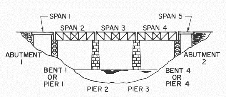 Bridge element numbering sequence
The superstructure element numbering system should include the spans, the main beams, the secondary elements (diaphragms, transoms, etc) and, in the case of a truss, the panel points. The spans should be numbered consecutively, with Span 1 located at the beginning of the bridge. Multiple beams should be numbered consecutively from left to right facing in the route direction (refer to Figure 2, page 9).
The crossbeams should be denoted consecutively from the beginning of the bridge with a letter, with the first crossbeam (the near abutment diaphragm) labelled as A, leading to the far abutment diaphragm.
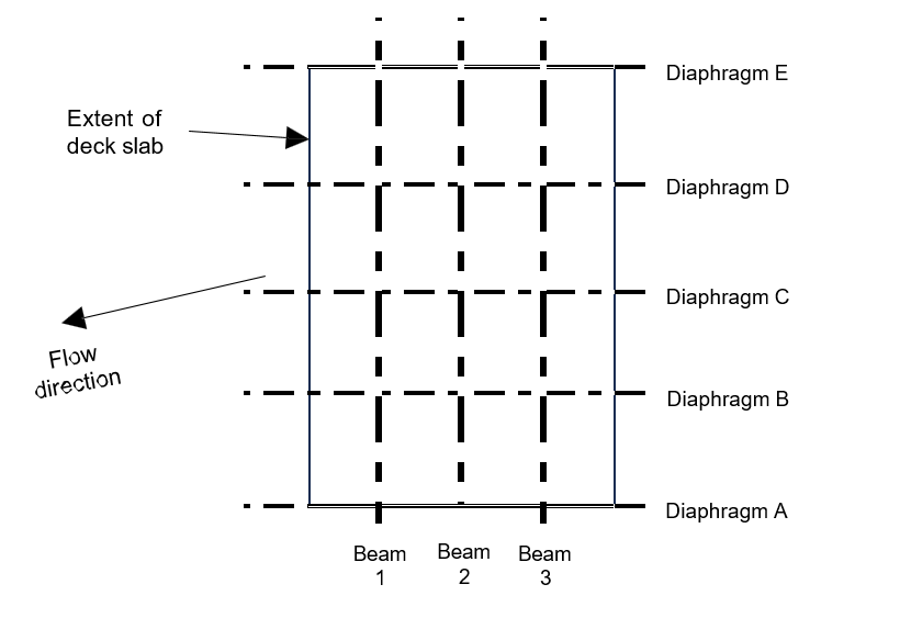 Example of one span/3 beam bridge element numbering system
For trusses, the panel numbers should be numbered similarly to the beams, beginning with Panel Point 1. Label both the left and right trusses. Points in the same vertical line have the same number.
Open Data Kit (ODK) Data Collection System for Tripltek Tablet
The ODK data collection format has been set up for the logical process of inspecting the bridge approaches and deck; the superstructure; the substructure and finally the watercourse/features below the bridge. The set-up is as follows:
| Page | Set-up |
|---|---|
| 1-3 | General data on bridge with salient features |
| 4 | Roadway approaching the bridge and deck surfacing elements |
| 5 | Span information* – Number of spans
|
| 6 | Roadway departing the bridge |
| 7 | Other pertinent details – waterway features, etc. |
*All data input for Span 1 follows through to the last span so only those unique features (such as span length, pier height) need to be amended for each span.
Then starts the serious condition assessment with a loop feature for each category of functional group; as follows (note that the loop can continue until all serious defects on the individual elements (or groups, if common defects are found)) have been identified and recorded:
- Bridge Element Condition Assessment > 1 (and 2) assesses the condition of the features on the approach, bridge deck and departing road sections.
- Waterway Condition Assessment > 1 (and 2 to N linked to Span Number) assesses the condition of the waterway elements below the bridge.
- Superstructure Condition Assessment > 1 (to N with minimum for single condition reference per span).
- Substructure Condition Assessment > 1 (to N with minimum for single condition reference per span).
In order to avoid confusion as to whether an element or group feature has been inspected and found to be in good condition throughout, one Condition Assessment must be completed with 100 inserted into the ‘0(%) – as new’ state per span if no defects are found.
For a particular span, a group of elements can be recorded and their condition state noted in a “group” Smart Flag when the condition state is found on all the elements; with any more serious condition state (defect) recorded in a separate Smart Flag for an individual element.
For example, if all the steel deck beams in a span are in a similar state of defective corrosion this can be recorded in a Smart Flag with the comment “Refers to all beams – light corrosion of the steel beams” with a separate Smart Flag for the outer beam where a more serious corrosion state exists below a defective deck drain. A further Smart Flag needs to be raised for the deck drain repair.
Bridge Element Condition Assessment
To give full flexibility to the Inspector for the input of condition data the Condition Assessments have been set up in a “loop” so that as many Condition Assessments as required to fully describe the condition of the Elements and the defects found on them can be used.
| Element | Span No. | Location | Unit | Length | Height | Condition State | |||
| 0 | 1 | 2 | 3 | ||||||
| Note 1 | Note 2 | Note 3 | Note 4 | Note 4 | Note 4 | Note 4 | |||
Note 1: All Elements described in tables in the Collection of Inventory Information - Work Instruction article.
Note 2: Each Span must be given a Condition Assessment with defects described separately. If there are no defects and the span is in good condition 100% must be inserted in Condition State 0.
Note 3: Location is given above (Bridge element numbering system). Sections of Main Beam can be given as 1A to 1B and likewise sections of secondary elements can be given as B2 to B3.
Note 4: Condition State MUST add up to 100%.
Particular Defect “Smart Flags” and Photographs:
| How many Smart Flags | (insert number) | |
| Smart Flag # | Safety | Comment on Smart Flag |
| Failure | ||
A “safety” Smart Flag must be used if, in the opinion of the Inspector, a defect impacts the integrity of the structure to such a degree that the safety of the public or structure is jeopardised.
Sequence of Condition Assessment
The sequence for a bridge of an average length and complexity is as follows:
- Inspect roadway and deck elements
- Inspect superstructure elements and bearings
- Inspect substructure elements
- Inspect riverbed and slopes
After or during the inspection, the Bridge Inspector must take at least one photo of every element group.
1. Roadway and Deck Elements
The inspector should check:
- The pavement for unevenness, settlement, or roughness (shown below).
- Shoulders, slopes, drainage, and the approach guardrail.
- The deck and sidewalks for various defects, noting the size, extent, severity, and location of each element. The location should be referenced using the span number or side.
- The expansion joints for sufficient clearance and for an adequate seal.
- The safety features, including barriers and handrails (shown below), signs and lighting are present and identify their condition.
| Condition states of pavement | |||
|---|---|---|---|
| Condition State 0 | Roadway is smooth, no rutting and only small roughness. |  |  |
| Condition State 1 | Roadway has small, visible rutting, longitudinal unevenness that can be fixed with local repair. |  |  |
| Condition State 2 | Roadway has ruts, cracking and small holes. People need to pay attention when crossing, but no safety issues. Needs resurfacing. |  |  |
| Condition State 3 | Hollow ruts and holes. Safety of a road user is affected and whole pavement needs replacement. |  |  |
| Condition states of barriers and handrails | |||
|---|---|---|---|
| Condition State 0 | The elements have no remarkable defects or wearing marks. The overall appearance is as good as new. |  |  |
| Condition State 1 | The elements have minor superficial damages and deformations. Wearing and deterioration processes have occurred. The overall appearance is clean, but pitting corrosion can occur. |  |  |
| Condition State 2 | The elements have defects, like pitting corrosion, but the severity of the damages does not affect functional requirements. |  |  |
| Condition State 3 | The element has defects that affects the safety of users. |  |  |
2. Superstructure Elements
The superstructure must be inspected thoroughly since the failure of a main supporting member could result in the collapse of the bridge. The most common forms of main supporting members are:
- Girders
- Floor Beams and Stringers
- Slabs
- Trusses
- Eye bar Chains
- Arch Ribs
- Frames
- Bearings must be inspected thoroughly since they provide a critical link between superstructure and the substructure. For instance, one will need to record the difference between a rocker tilt and a fixed reference line, noting the direction of the tilt in the case of a rocker bearing. For an elastomeric bearing, for instance, any loss of section or major wear should be noted as a deterioration in condition.
- Utilities (pipes, ducts, etc.)
- Anchorages
| Condition states of concrete superstructure elements | |||
|---|---|---|---|
| Condition State 0 | The concrete elements have no remarkable defects or wearing marks. The overall appearance is as good as new. |  |  |
| Condition State 1 | The elements have minor superficial damages, like honeycombing and hairline cracks. Wearing and deterioration processes have occurred. |  |  |
| Condition State 2 | The elements have defects, like corrosion, but the severity of the damages does not affect functional requirements. |  |  |
| Condition State 3 | The elements have severe defects, like peeling and heavy corrosion, the damages do affect functional requirements. |  |  |
| Condition states of steel superstructure elements | |||
|---|---|---|---|
| Condition State 0 | The steel elements have no remarkable defects or wearing marks. The overall appearance is as good as new. |  |  |
| Condition State 1 | The elements have minor superficial damages, like deformation or painting defects. Wear has occurred. |  |  |
| Condition State 2 | The elements have defects, like pitting corrosion, but the severity of the damages does not affect functional requirements. |  |  |
| Condition State 3 | The elements have severe pitting corrosion, that does affect functional requirements. |  |  |
3. Substructure Elements
The substructure supports the superstructure and is made up of abutments, piers and bents, footings, and piles. If the “as-built” plans are available, the field-measured dimensions of the substructure units should be compared to those presented on the plans. Since the primary method of bridge inspection is visual, all dirt, leaves, animal waste, and debris should be at least partially removed to allow close observation and evaluation. Substructure units should be checked for:
- Settlement by sighting along the superstructure and plumbing vertical faces.
- In conjunction with scouring inspection of the waterway, the substructure unit should be checked for undermining, noting both its extent and location.
| Condition states of abutments | |||
|---|---|---|---|
| Condition State 0 | Elements have no remarkable defects, settlements or scouring. The overall appearance is as good as new. |  |  |
| Condition State 1 | Elements have small visible defects, settlements or scouring. The overall appearance is as good, but small repairs are needed. |  |  |
| Condition State 2 | Elements have remarkable defects, settlements or scouring. The overall appearance is satisfactory and elements function as intended, but repairs are needed. |  |  |
| Condition State 3 | Elements have critical defects, settlements or scouring. The elements may not function as intended and replacement is needed. |  |  |
4. Channel and Waterway Elements
Waterways are dynamic in nature, with their volume of flow and their path continually changing. Thus, the bridges passing over them must be inspected for the effects of these changes:
- Maintain a record of the channel flow profile and alignment, noting any meandering of the channel both upstream and downstream.
- Report any skew or improper location of the piers or abutments, that can be related to scour.
Smart Flags
The use of a “safety” Smart Flag must be used if, in the opinion of the Inspector, a defect impacts the integrity of the structure to such a degree that the safety of the public or structure is jeopardised. The addition of a smart flag and deterioration process assessment to the main damages of the bridge is necessary to give an in-depth view and evaluate bridge reliability and safety. Safety is defined as user safety, and the outcome (failure mode) is always an accident. The evaluation method of reliability is connected to failure modes in vulnerable zones of structures and quantitative modelling of bridge damage processes.
By accurately identifying defects, potential failures can be predicted. As a Bridge Inspector, it is crucial to flag these defects with relevant comments, highlighting elements that require urgent attention or further structural assessment.
Observing a defect on a bridge often indicates active damage processes. Analyzing these processes and their relationship to the observed defects helps identify the root causes. Understanding damage processes is essential for predicting performance, planning preventive maintenance, and considering potential rehabilitation. Reliable information on these processes allows for optimised inspection and maintenance strategies, aligned with the exposure classes defined during the design phase.
Vulnerable Zones
To assess deterioration processes, the evaluation should be tailored to the type of damage, its cause, and the material of the affected structural element. Most damages can be linked to specific defects or observations. However, some damages are merely symptoms and do not impact the structure’s reliability.
Nearly all deterioration processes related to concrete structures can affect any part of a concrete bridge. However, it is important to note that not all parts of the bridge are equally critical in terms of consequences. For example, load-bearing elements have regions that are particularly vulnerable and require special attention, which will be discussed further.
The proposed segmentation of the superstructure in the longitudinal direction (partitioning of an element into regions with different vulnerability) is based on the Concrete Details Vulnerability Manual, and the Long-Term Bridge Performance Program Protocols, Version 1:
- High moment regions
- Sagging (label HMS region)
- Hogging (label HMH region)
- High shear regions (label HS region)
- Construction joint (rigid type) (label CJ region)
- Shear key (label SK region)
- Hinges (label HG region)
- Anchorage zones (label AN region)
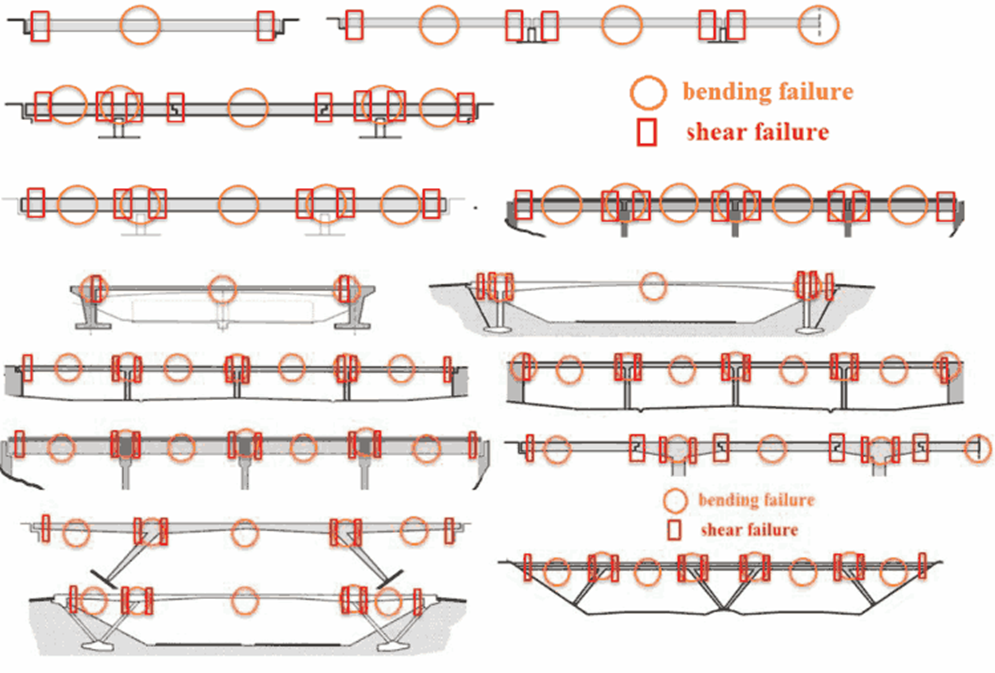 Vulnerable zones for different types of girder and frame bridges
Conceptual weaknesses may also be associated with some of the above-mentioned vulnerable zones. One such example is poor shear capacity in high shear regions in old concrete bridges. This conceptual weakness is due to limited understanding of the shear phenomena given in old design codes.
Furthermore, it should be noted that elements of the substructure support the superstructure, implying that their failure might lead to a total collapse. In general, a substructure might fail in crushing or buckling failure mode. In addition, bearing areas are exposed to splitting forces. Pier caps (if they exist) are generally exposed to high shear stresses making them particularly vulnerable. Elements of substructures are mainly exposed to sudden events e.g., impact, scour and earthquake. Typical locations of vulnerable zones related to piers are presented below along with their relationship to an anticipated failure mode.
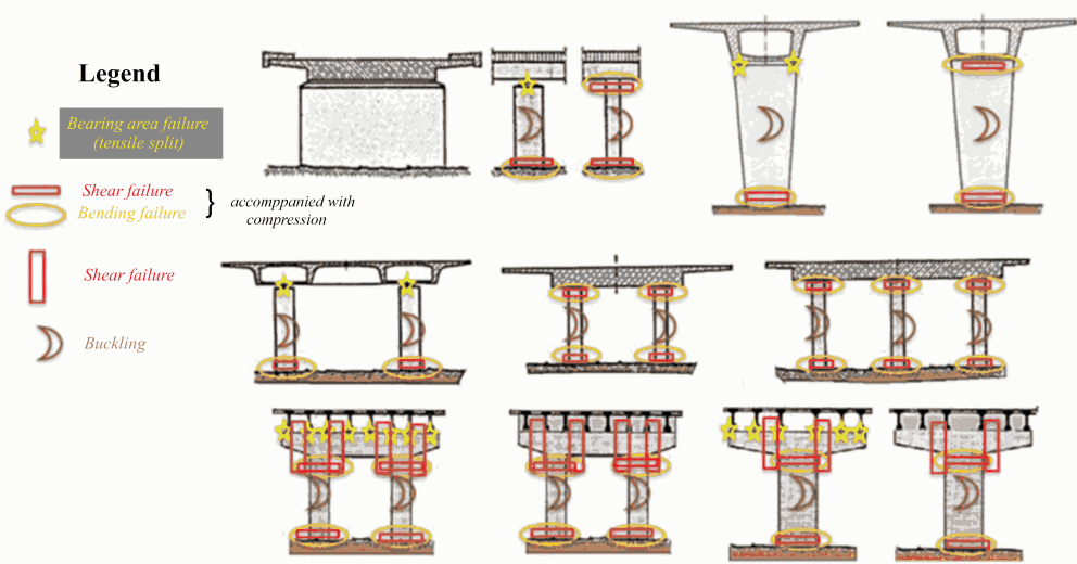 Vulnerable zones related to substructure
In addition to the load bearing function there are elements that give protection and comfort, these elements are related to nearly all bridge types. It should be noted that malfunction of these elements might jeopardise the load-bearing elements of the bridge (durability issues) and/or impose severe consequences themselves. The level of service generally depends on the adequate function of these elements (traffic safety issues). Below, vulnerable areas are listed as checklists that may be used during inspection.
- Bearings
- Sufficient ability to allow movement, considering the temperature of the superstructure.
- Correct position of the bearings themselves and parts of the bearing relative to each other.
- Uncontrolled movement of the bearing, as predicted by Movement Indicator provided in slide-guide and Free Bearing (Pot & Spherical).
- Fracture, cracks, and deformations of parts of the bearings.
- Cracks in the bedding or in adjacent parts of sub- and superstructure.
- The condition of the anchorage.
- The condition of sliding or rolling surfaces.
- The condition of the anticorrosive protection against dust, and of the sealings.
- Concrete hinges
- Developed more than 100 years ago and if correctly executed they perform very well throughout the world. Concrete hinges are characterised by high load- carrying capacity and a moderate rotational capacity. Concrete cracking in the throat of the Freyssinet (un-reinforced) hinge and risk of impact shear loading in the Mesnager (reinforced) hinge are important considerations when assessing or predicting concrete hinge performance.
- Expansion Joints
- Damage to the anticorrosive protection.
- Cracks due to fatigue in steel members.
- Damage to seals.
- Workability of the linkage (proper function).
- Obstruction or damage of the drainage system
- Drainage
- As a sub-component of the equipment category, comprises of permanently installed drains and the associated piping systems. The inspection should verify proper deck slopes and proper functioning of kerb channels, drainage inlets, pipes and outlets, and possible drain holes for drainage of voids. Blockage of drainage may create a serious traffic hazard as well as result in severe deterioration.
- Waterproofing is usually not visible, i.e., the condition has to be assessed from possible consequential damage on the neighbouring components such as:
- Leaking decks/wet spots beneath the superstructure
- Finding of protective concrete wash out
- Swelling of the pavement
- Cracking of the pavement
- Pavement/Overlay
- Cracks, unevenness, holes, and swelling
- Rutting
- Lack of friction
- Joint failure
- Improper drainage
- Barriers, windscreens, and signs
- Damages from impact
- The condition of the anticorrosive protection
- Missing or loose bolts
- The condition of the anchorage
- The condition of the concrete
- Visual appearance (readability, reflection, lighting etc.)
- Installations typically comprise of lighting (typically light poles), electro-mechanical dehumidification systems (primarily on signature bridges), Structural Health Monitoring Systems (primarily on signature bridges), hydraulic opening arrangement, and possible utility lines fixed/fastened on the bridge. Their vulnerability shall be evaluated case by case.
Hidden Defects
Sudden weight restrictions and emergency closures on roadway bridges are often because of hidden defects. These defects that are hidden from sight (inspection within touching distance) or are not obvious on the first observation/inspection. A guidance for detecting and managing hidden defects in bridges consists of a three-step procedure comprising of risk review, risk assessment, and risk management. As part of the risk review, two key questions must be asked during the review of existing information: “What do the records say?” and “What is not recorded?” Also, two questions must be asked on site during inspections: “What can I see?” and “What can I not see?”
The typical hidden defects for concrete girder and frame roadway bridges can be summarised as:
- Superstructure
- Within the concrete body
- Reinforcement
- Prestressing wires/stands and anchorages
- Voided and cellular structures
- Half-joints
- Obscure surfaces
- Concrete hinges
- Temporary works
- Bearings and expansion joints
- Poor access
- Inspection at the ‘wrong time’
- Uninspectable items
- Drainage
- Waterproofing
- Substructure
Road and Work Safety
The protection and safety of experts and environment are the essential on every work site and should be prioritized at all times during field operations.
Working on or near roads is extremely hazardous and the following rules must be observed by all personnel:
- Before commencing inspection at the site ensure that all personnel are wearing high visibility vests, everyone knows the direction of traffic on all the lines, where to take refuge if a vehicle approaches and where are unprotected or unsafe areas.
- During the inspection do not walk on or near the road without a reason and always walk towards oncoming vehicles.
- Whenever crossing roads make sure all the lanes are clear before crossing.
- When operating any machine or equipment, make sure you are aware of potential hazards (roads, power lines, other workers etc.), never step backwards without looking, and always look around you.
The best way of keeping work safety, is planning. The checklist of general safety requirements:
- If a bridge site is identified as having security problem, the inspection team should be escorted by the security personnel from the local police force. Necessary procedures should be in place to track the contact location of the team during the survey period.
- One should be familiar with the full requirements of the inspection work including personal clothing, footwear, gloves, helmets, overall falsework and access equipment.
- The working order of all tools, machines and equipment should be ensured.
- If needed, plan and arrange road closures and suitable traffic management procedures.
- Ensure that a first aid kit is available.
- Avoid involving persons who are not qualified for the tasks or operating particular equipment.
- During the inspections, identify and locate all utilities existing at the site (water, sewerage, electricity, signals, communications, gas etc.) If any utilities are affected, take measures by informing the relevant authorities.
- Personnel under the influence of alcohol or any medication which impairs alertness or causes drowsiness are not allowed to work on site or to operate any equipment.
- Generally, all the work should be carried out as per industry standards or good practice.
Photographs for Bridge Inspections
In addition to data collection, inspections must include photographing the main elements and damages, starting with the most critical ones. It is recommended to take photographs in the same sequence as the condition inspections, beginning with general photos from above and then moving below the structures.
Use a tablet, mobile, or DSLR camera in landscape mode (horizontally) to capture the widest views possible. Only use portrait mode (vertically) when photographing tall subjects, such as a close-up of a pier. Regularly check that the lens is clean of dirt and grease, wiping it with wet and dry tissues as needed. Avoid taking photos against bright sunlight; if necessary, use your free hand to cast a shade over the lens.
For general photos, ensure to include at least six key areas, as follows:

| Picture 1 | Approach view of the bridge from the start (remember which end is the start, and which is the end) |
| Picture 2 | Closer view of the bridge deck in one photo with the first expansion joint included. Also, other structures like barriers, parapets and trusses may ideally fit in the photo. |
| Picture 3 | Similar approach view of the bridge from the other end. |
| Picture 4 | Similar closer view of the bridge deck from that other end, including the last expansion joint and the other elements too. |
| Picture 5 | Sideview of the whole bridge from the upstream side. For taking the photo go as centre as you can, but if it isn't feasible, it can also be taken from the riverbank. Try to fit the abutments and closest banks too. |
| Picture 6 | Similar sideview of the whole bridge from the downstream side. |
Additional general pictures of the whole bridge are optional, but may be useful.
For the element condition assessment photos, while filling the form or separately, the sequence should be as follows:
- Take photos of roadway and deck surface elements
- Take photos of superstructure elements and expansion joints
- Take photos of substructure elements and bearings
- Take photos of riverbed and slopes
Those photos are always required when there is something that is not 100% in the “as new” condition. If everything is perfect, no additional assessment photos are required, but can be added optionally.
Quality Assurance
If the data collection is being undertaken by a consultant, DoWH reserves the right for one AMB staff member to join the Consultant’s on-site survey team(s) for quality review purposes. The Consultant is to allow for one (only) seating place in its primary survey vehicle to accommodate an AMB staff member and shall provide a minimum of five business days notice of any change of travel dates that have been previously agreed with DoWH (eg. through approval of the Consultant’s Workplan). All direct costs (eg. travel airfares, accommodation, per diems etc) incurred by a DoWH staff member accompanying the Consultant’s survey team are the responsibility of the client.
Stakeholders
| Stakeholder | Role |
|---|---|
| DoWH AMB | The Asset Management Branch is responsible for this specification and utilising the data for the support of programme development and further analysis. |
| Provincial Works Manager (PWM) | The PWM is the most senior DoWH role based in each province and should be advised of any data collection to be done on national roads in their province. |
Support
The following provides contacts for each of the main technical systems used by the DoWH AMB.
| System | ||
|---|---|---|
| ThinkProject Asset & Works Manager | The core system of the DoWH Road Management System | edmond.li@ghd.com |
| Mapillary | For uploading and accessing network video | remson.maea@pngroads.com |
| GoPro MAX | For the recording of network video | remson.maea@pngroads.com |
| TotalPave | For the recording of pavement (network) roughness | rexie.rei@pngroads.com |
| MetroCount | MetroCount counters and software for the recording of traffic counts | remson.maea@pngroads.com |
| KnowledgeOwl | Knowledgebase for the DoWH asset management and other related activities and requirements | elliot.mcbride@ghd.com |
References and Additional Reading
Links to further support documents, manuals, publications and other content are included in the table below.
| Reference Name / Description |
|---|